Product Description
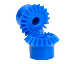
Spiral Bevel Gear Reducer Bevel Gearboxes 1 to1, 2 to1, 3 to 1 Ratio T Series Small Right Angle Gearbox
Product Description
Technical data:
1. Power: 0.37-200 (KW)
2. Output Speed: 11-226RMP,
3. Torque: 400-56000 (N. M)
4. Transmission stage: Three stage
Applications:
The products are widely applied in electricity, coal, cement, metallurgy, harbor, agriculture, shipping, lifting, environment protection, stage, logistic, weaving, paper making, light industry, plastics and other regions
1. We accept sample order.
2. We undertake the problems due to quality.
3. We supply detail answers about technical questions.
4. We are the manufacturer so we could supply the products as soon as possible.
5. At the instance of our dear customer, we can do the customized gear boxes for clients.
Detailed Photos
Commercial information:
1. MOQ: 1 set
2. Packing method: Polywood
3. Delivery lead time: 10-25 days
4. Price terms: FOB, CIF, EXW
5. Payment method: T/T, 30% in advance, 70% balance before delivery
6. Shipping port: HangZhou
7. OEM: We accept customized products as per your special requirement.
8. Xihu (West Lake) Dis.lines for the Selection: Usually we can select 1 machine which is suitable for you with some informations from you, such as ratio/motor speed/mounting dimension/ output torque etc.
9. If the minimum order amount is in excess of $10000, there are preferential
| input power | 0.018-96kw |
| ratio | 1-3 |
| permissable torque | 11-607N.M |
| mounting type: | footmounted |
| usage: | change direction |
Product Parameters
| Models | Input Power | Ratio | Max. Torque | Weight(kg) | Output Shaft Dia.(k6) |
| T2 | 0.014KW~1.79KW | 1~2 | 11 | 2 | Φ15 |
| T4 | 0.026KW~4.94KW | 1~2 | 31 | 10 | Φ19 |
| T6 | 0.037KW~14.9KW | 1~3 | 94 | 21 | Φ25 |
| T7 | 0.042KW~22KW | 1~3 | 139 | 32 | Φ32 |
| T8 | 0.064KW~45.6KW | 1~3 | 199 | 49 | Φ40 |
| T10 | 0.11KW~65.3KW | 1~3 | 288 | 78 | Φ45 |
| T12 | 0.188KW~96KW | 1~3 | 607 | 124 | Φ50 |
| T16 | 0.40KW~163KW | 1~3 | 1073 | 188 | Φ60 |
| T20 | 0.69KW~234KW | 1~3 | 1943 | 297 | Φ72 |
| T25 | 1.4KW~335KW | 1~3 | 3677 | 488 | Φ85 |
Ratio: 1:1, 1.5:1, 2:1, 2.5:1, 3:1
Packaging & Shipping
Company Profile
After Sales Service
| Pre-sale services | 1. Select equipment model. |
| 2.Design and manufacture products according to clients’ special requirement. | |
| 3.Train technical personal for clients | |
| Services during selling | 1.Pre-check and accept products ahead of delivery. |
| 2. Help clients to draft solving plans. | |
| After-sale services | 1.Assist clients to prepare for the first construction scheme. |
| 2. Train the first-line operators. | |
| 3.Take initiative to eliminate the trouble rapidly. | |
| 4. Provide technical exchanging. |
FAQ
FAQ:
1.Q:What kinds of gearbox can you produce for us?
A:Main products of our company: UDL series speed variator,RV series worm gear reducer, ATA series shaft mounted gearbox, X,B series gear reducer,
P series planetary gearbox and R, S, K, and F series helical-tooth reducer, more
than 1 hundred models and thousands of specifications
2.Q:Can you make as per custom drawing?
A: Yes, we offer customized service for customers.
3.Q:What is your terms of payment ?
A: 30% Advance payment by T/T after signing the contract.70% before delivery
4.Q:What is your MOQ?
A: 1 Set
Welcome to contact us for more detail information and inquiry.
If you have specific parameters and requirement for our gearbox, customization is available.
| Application: | Machinery, Industry |
|---|---|
| Function: | Change Drive Direction, Speed Reduction |
| Layout: | Right Angle |
| Hardness: | Hardened |
| Installation: | Vertical Type |
| Step: | Single-Step |
| Samples: |
US$ 1/Piece
1 Piece(Min.Order) | |
|---|
| Customization: |
Available
| Customized Request |
|---|
Can miter gears be used in high-torque applications?
Miter gears can indeed be used in high-torque applications, although there are certain considerations to keep in mind. Here’s a detailed explanation:
Miter gears are capable of transmitting significant amounts of torque due to their tooth design and load distribution characteristics. The interlocking tooth design of miter gears allows for efficient torque transfer between mating gears, minimizing power loss. Additionally, the load distribution across multiple teeth helps to distribute the torque and reduce stress concentrations on individual teeth.
However, the suitability of miter gears for high-torque applications depends on several factors:
1. Tooth Design:
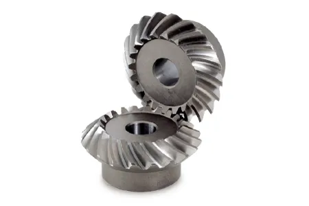
The tooth design of miter gears plays a crucial role in their torque-carrying capacity. Spiral bevel gears, with their curved teeth, are particularly well-suited for high-torque applications. The curved tooth profile allows for increased contact area and smoother engagement, resulting in improved torque transmission and higher load capacity compared to straight bevel gears.
2. Gear Material and Hardness:
The material and hardness of the miter gears are important considerations for high-torque applications. The gears should be made from materials with high strength and wear resistance, such as alloy steels. Proper heat treatment and surface hardening techniques can further enhance the gear’s ability to withstand high torque loads and minimize wear.
3. Lubrication and Cooling:
Effective lubrication is essential for high-torque applications to reduce friction and heat generation. Lubricants help to minimize wear and ensure smooth gear operation. In some cases, additional cooling mechanisms, such as forced-air or liquid cooling, may be required to dissipate heat generated during high-torque operation.
4. Gear Size and Diameter:
The size and diameter of the miter gears can impact their torque-carrying capacity. Larger gears generally have larger contact areas and can handle higher torques. However, it’s important to consider the available space and operating constraints when selecting the gear size.
5. Backlash Control:
Backlash, the clearance between mating teeth, can affect the smoothness and accuracy of torque transmission. In high-torque applications, maintaining proper backlash control becomes even more critical to prevent any unwanted movement or play that could impact performance and reliability.
By considering these factors, engineers can select miter gears that are suitable for high-torque applications. It’s important to consult gear manufacturers and design experts to ensure the gears are properly sized, designed, and manufactured to handle the specific torque requirements of the application.

How do you calculate the gear ratio in a miter gear assembly?
The gear ratio in a miter gear assembly can be calculated by considering the number of teeth on the gears involved. Here’s a step-by-step explanation:
1. Determine the Number of Teeth:
Identify the number of teeth on both the driving gear (input gear) and the driven gear (output gear) in the miter gear assembly. The number of teeth can usually be found in the gear specifications or by physically counting the teeth.
2. Calculate the Gear Ratio:
To calculate the gear ratio, divide the number of teeth on the driven gear (output gear) by the number of teeth on the driving gear (input gear). The formula for calculating the gear ratio is:
Gear Ratio = Number of Teeth on Driven Gear / Number of Teeth on Driving Gear
3. Simplify the Ratio (Optional):
If the resulting gear ratio is a fraction, it can be simplified to its simplest form. Divide both the numerator and the denominator by their greatest common divisor to simplify the ratio.
4. Interpret the Gear Ratio:
The gear ratio indicates the relationship between the rotational speed or angular velocity of the driving gear and the driven gear. It represents how many times the driven gear rotates for each rotation of the driving gear. For example, a gear ratio of 2:1 means that the driven gear rotates twice for every rotation of the driving gear.
5. Consider the Significance:
The gear ratio has practical implications in determining the mechanical advantage and speed reduction/amplification in a miter gear assembly. A gear ratio greater than 1 indicates a speed reduction and increased torque, while a gear ratio less than 1 indicates a speed amplification and decreased torque.
In summary, the gear ratio in a miter gear assembly is calculated by dividing the number of teeth on the driven gear by the number of teeth on the driving gear. This ratio represents the relationship between the rotational speeds of the gears and provides insights into the mechanical advantage and speed transformation in the gear assembly.
What is the purpose of using miter gears in mechanical systems?
Miter gears serve several purposes and offer distinct advantages when used in mechanical systems. Here’s a detailed explanation:
1. Change of Shaft Direction:
One of the primary purposes of using miter gears is to facilitate a change in the direction of shaft rotation. When two miter gears with intersecting shafts are meshed together, they allow the transmission of rotational motion at a 90-degree angle. This enables the redirection of power and torque to a different axis, which can be crucial for the functioning of various mechanical systems.
2. Power Transmission:
Miter gears are designed to efficiently transmit power between intersecting shafts. The meshing of the gear teeth ensures a smooth transfer of rotational energy, enabling the transmission of torque and rotational motion from one shaft to another. This makes miter gears suitable for applications where power needs to be transmitted between perpendicular axes.
3. Speed Reduction or Increase:
By using miter gears with different numbers of teeth or by combining them with other gears, speed reduction or speed increase can be achieved. The gear ratio between the miter gears determines the change in rotational speed. This allows for the adjustment of output speed to match the requirements of the mechanical system, ensuring optimal performance.
4. Compact Design:
Miter gears are known for their compact design, making them valuable in applications where space is limited. The intersecting shafts and the conical shape of the gears allow for efficient power transmission while occupying a small footprint. This compactness is particularly beneficial in devices and systems where size and weight constraints are critical factors.
5. Alignment and Torque Distribution:
Miter gears help maintain proper alignment and torque distribution between intersecting shafts. The gear teeth engagement ensures accurate alignment, which is essential for smooth and efficient operation. Additionally, the equal distribution of torque among the teeth of miter gears helps prevent excessive stress on individual gear teeth, promoting longevity and reliability.
6. Applications:
Miter gears find applications in a wide range of mechanical systems, including:
- Power transmission systems
- Automotive differentials
- Mechanical clocks
- Robotics
- Printing machinery
- Woodworking tools
- Camera lenses
In summary, the purpose of using miter gears in mechanical systems is to facilitate a change in shaft direction, transmit power efficiently, achieve speed reduction or increase, maintain a compact design, and ensure proper alignment and torque distribution. These characteristics make miter gears suitable for various applications, contributing to the functionality and performance of mechanical systems.


editor by CX 2023-10-23