Product Description
Product Description
| Car Fitment | Jeep Wrangler |
| OE No. | D44513JK |
| Speed Ratio | 8*41 |
| Type | Differential Gear |
| Material | 20CrMnTi/ 8620 |
| Hardness | HRC58-62 |
| Treatment | Carburizing,Hardening, tempering,high frequency treatment,black coating,zincing,nickelage |
We can make all kinds of CZPT Wheel Pinion as per your drawing or sample by our DHL account.
| D3571 | 11/41 | CJ5/7/8 CZPT 30 FRONT STD.3.73 72-86 |
| D3571R | 11/41 | YJ FRONT CZPT 30 REVERSE 3.73 |
| D3571TJ | 11/41 | TJ (97-06) FRONT CZPT 30 3.73 (SHORT STYLE) |
| D3571 | 10/41 | CJ5/7 CZPT 30 FRONT STD.4.10 |
| D3571R | 10/41 | YJ(87-95) FRONT CZPT 30 REVERSE 3.73 XJ(84-91) |
| D3571TJ | 10/41 | TJ (97-06) FRONT CZPT 30 4.10 (SHORT STYLE) |
| D3 0571 | 9/41 | CJ5/7/8 CZPT 30 FRONT STD.4.56 72/86 |
| D3 0571 R | 9/41 | YJ(87/95) FRONT CZPT 30 REVERSE 4.56 XJ(84-91) |
| D3 0571 TJ | 9/41 | TJ(97-06( FONT CZPT 304.56 (SHORT STYLE) XJ(92-01) |
| D30488 | 8/39 | CJ5/7 CZPT 30 FRONT STD.4.88 72-86 |
| D30488R | 8/39 | YJ(87-95) FRONT CZPT DANA 30 REVERSE 4.88 XJ(84-91) |
| D30488TJ | 8/39 | TJ FRONT CZPT 30 4.88 (SHORT STYLE) |
| D35712(47715) | 18/49 | |
| D35373 | 11/41 | YJ/TJ CZPT 35 REAR 3.73 |
| D35411 | 10/41 | YJ87-95 /TJ97-06/XJ93-07 CZPT 35 REAR 4.10 |
| D35456 | 9/41 | YJ/TJ CZPT 35 REAR 4.56 |
| D35488 | 8/39 | YJ/TJ CZPT 35 REAR 4.88 |
| D44373 | 11/41 | TJ REAR CZPT 44 3.73 |
| D44409 | 11/45 | TJ REAR CZPT 44 4.10 22745 |
| D44456R | 9/41 | DANA 44 4.56 REVERSE |
| D44455 | 11/50 | TJ REAR CZPT 44 4.56 22105 |
| D44455X | 11/50 | |
| D44488R | 8/39 | DANA 44 4.88 REVERSE |
| D44489 | 9/44 | TJ REAR CZPT 44 4.88 23053 |
| D44489X | 9/44 | |
| D44488X | 8/39 | RUBICON FROUT/REAR CZPT 44 4.88 |
| D44513R | 8/41 | DANA 44 5.13 REVERSE |
| D44513 | 8/41 | TJ REAR CZPT 44 5.13 |
| D44513X | 8/41 | RUBICON FROUT/REAR CZPT 44 5.13 |
| D5 0571 | Sep-41 | |
| D50488 | Aug-39 | |
| D5571 | Aug-41 | |
| D44-4-373 | Nov-41 | 85719 |
| D44-4-342 | Dec-41 | 80364 |
| D44-4-353 | 46/13 | 75945 |
| D44-4-307 | 43/14 | |
| D44-4-346 | Nov-38 | 84707 |
| D44463 | 37*8 | 74960 |
| D44410 | 41*10 | 80320 |
| D44373 | 41*11 | 22736X |
| D44456 | 41*9 | 85713 |
| D44323 | 42*13 | 28744 |
| D44331 | 43*13 | 23592X |
| D44307 | 43*14 | 22106X |
| D44354 | 46*13 | 22856X |
| D44427 | 47*11 | 23064 JEEP WILLYS 11*47 8125051 ANO 1985(CJ6) |
| D44427X | 47*11 | CHRYSLER |
| D44538 | 43*8 | |
| D44-3-342 | 41*12 | 660150 |
| D6571 | 37*9 | 74905 CZPT 3F,D60-411,9X37 |
| D6571 | 41*10 | 24807(FORD250) |
| D6571 | 41*11 | 25538 |
| D6 0571 | 46*13 | 24813 |
| D6 0571 | 41*9 | FORD F250 |
| D6 0571 X | 41*9 | |
| D6571 | 41*8 | |
| D6571R | 41*8 | |
| D60586 | 41*7 | |
| D6571 | 43*8 | Isuzu NHR,D60-586 7*41 |
| D6571R | 43*8 | |
| D60488 | 39*8 | |
| D60488R | 39*8 | |
| D70488 | 39*8 | 72148 |
| D7571 | 41*10 | 72153 |
| D7571 | 41*11 | 72159 |
| D7571 | 41*8 | 72150 C30/P30 F350 41*8 5.3 |
| D7 0571 | 41*9 | 72152 CZPT F350 75-80 |
| D7 0571 X | 46*13 | 72168 |
| D70-1-410 | 41*10 | 72154 CZPT F350 BAJA 75/80 41*10 4.10 |
| D70586 | 41*7 | 72156 D300/P300 41*7 5.86 |
| D75-410 | 41*10 | BA457171-X CZPT Cargo |
| D75-462 | 37*8 | BA457104-X |
| D8571 | 41*8 | 73168 |
| D8571 | 41*10 | 73200 |
| D8571X | 41*40 | |
| D80430 | 43*10 | 76128 |
| D80488 | 39*8 | 76138 |
| D80463 | 37*8 | 73167 |
| D8571 | 41*11 | 76256 |
| D8 0571 | 46*13 | 73353 |
Company Profile
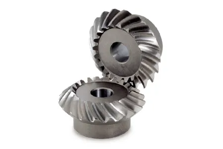
HangZhou CZPT Machinery is a professional manufacture of spiral bevel gear. The company has CNC milling machine, the GLEASON milling machine, rolling inspection machine, gear measuring center, a full set of metallographic analysis, inspection equipment and other related advanced equipment.
Our company owns gear measuring center equipped with advanced testing machines such as contourgraph, universal measuring microscope and full set netlaaographic analysis detector. According to various technical requirements and through procedures of sampling, special inspection and re-examination, multi-indexes of gears like observation, measurement and tracking can be completed.
With our high quality products, high credibility and trusty cooperation, aiming to be a highly specialized gear manufacturer of high level and all-directional service,we are looking CZPT to your business negotiation and our promising cooperation.
FAQ
Q1: Are your products standard?
A: Our model is standard, if you have specific demand, pls tell us the details.
Q2: What is you main categories?
A: Commercial Vehicles Like Isuzu,Nissan, Hino, CZPT ,Toyota , Mazda ,Suzuki, Agricultural Machinery and Electric Storage.
Q3: If we don’t find what we want on your website, what should we do?
A: You can email us the descriptions and pictures of the products you need, we will check whether we have them.
B: We develop new items every month, and some of them have not been uploaded to website in time. Or you can send us sample by express, we will develop this item for bulk purchasing.
Q4: What is your terms of payment?
A: T/T 30% as deposit, and 70% before delivery. We’ll show you the photos of the products and packages before you pay the balance.
Q5:Do you test all your goods before delivery?
Yes, we have 100% test before delivery.
| Application: | Motor, Electric Cars, Motorcycle, Machinery, Agricultural Machinery, Car |
|---|---|
| Hardness: | Hardened Tooth Surface |
| Gear Position: | External Gear |
| Manufacturing Method: | Cut Gear |
| Toothed Portion Shape: | Curved Gear |
| Material: | Cast Steel |
| Customization: |
Available
| Customized Request |
|---|
How do miter gears handle changes in direction and torque transmission?
Miter gears are specifically designed to handle changes in direction and torque transmission efficiently. Here’s an explanation of how they accomplish this:
1. Right Angle Transmission:
Miter gears are primarily used to transmit rotational motion at a 90-degree angle. When two miter gears with intersecting shafts are meshed together, they allow the input and output shafts to be positioned perpendicular to each other. This right angle transmission capability enables changes in direction within a compact space.
2. Interlocking Tooth Design:
Miter gears have teeth that are cut at a specific angle to match the gear’s cone shape. When two miter gears mesh, their teeth interlock and transfer torque between the gears. The interlocking tooth design ensures a smooth and efficient torque transmission, minimizing power loss and maximizing mechanical efficiency.
3. Bevel Gear Configuration:
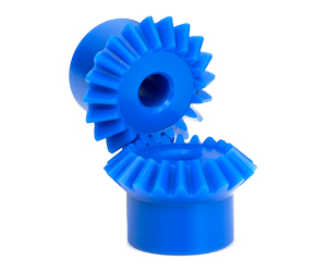
Miter gears belong to the bevel gear family, which includes straight bevel gears and spiral bevel gears. Straight bevel gears have straight-cut teeth and are suitable for applications with moderate torque and speed requirements. Spiral bevel gears have curved teeth that gradually engage, providing higher torque capacity and smoother operation. The choice between straight and spiral bevel gears depends on the specific application’s torque and performance requirements.
4. Meshing Alignment:
Proper alignment of miter gears is crucial for efficient torque transmission and smooth operation. The gears must be precisely positioned and aligned to ensure accurate meshing of the teeth. This alignment is typically achieved using precision machining and assembly techniques to maintain the desired gear contact pattern and tooth engagement.
5. Load Distribution:
When torque is transmitted through miter gears, the load is distributed across multiple teeth rather than concentrated on a single tooth. This load distribution helps to minimize tooth wear, reduce stress concentrations, and increase the overall load-carrying capacity of the gears.
6. Lubrication:
Proper lubrication is essential for the smooth operation and longevity of miter gears. Lubricants reduce friction and wear between the gear teeth, ensuring efficient torque transmission and minimizing heat generation. The type and method of lubrication depend on the specific application and operating conditions.
7. Backlash Control:
Backlash refers to the slight clearance between the mating teeth of gears. Miter gears can be designed with specific tooth profiles and manufacturing techniques to control backlash and minimize any unwanted movement or play. This helps maintain accuracy and precision in direction and torque transmission.
In summary, miter gears handle changes in direction and torque transmission through their right angle transmission capability, interlocking tooth design, bevel gear configuration, precise meshing alignment, load distribution across teeth, proper lubrication, and backlash control. These features make miter gears an effective choice for applications that require efficient and reliable direction and torque transmission.

How do you calculate the gear ratio in a miter gear assembly?
The gear ratio in a miter gear assembly can be calculated by considering the number of teeth on the gears involved. Here’s a step-by-step explanation:
1. Determine the Number of Teeth:
Identify the number of teeth on both the driving gear (input gear) and the driven gear (output gear) in the miter gear assembly. The number of teeth can usually be found in the gear specifications or by physically counting the teeth.
2. Calculate the Gear Ratio:
To calculate the gear ratio, divide the number of teeth on the driven gear (output gear) by the number of teeth on the driving gear (input gear). The formula for calculating the gear ratio is:
Gear Ratio = Number of Teeth on Driven Gear / Number of Teeth on Driving Gear
3. Simplify the Ratio (Optional):
If the resulting gear ratio is a fraction, it can be simplified to its simplest form. Divide both the numerator and the denominator by their greatest common divisor to simplify the ratio.
4. Interpret the Gear Ratio:
The gear ratio indicates the relationship between the rotational speed or angular velocity of the driving gear and the driven gear. It represents how many times the driven gear rotates for each rotation of the driving gear. For example, a gear ratio of 2:1 means that the driven gear rotates twice for every rotation of the driving gear.
5. Consider the Significance:
The gear ratio has practical implications in determining the mechanical advantage and speed reduction/amplification in a miter gear assembly. A gear ratio greater than 1 indicates a speed reduction and increased torque, while a gear ratio less than 1 indicates a speed amplification and decreased torque.
In summary, the gear ratio in a miter gear assembly is calculated by dividing the number of teeth on the driven gear by the number of teeth on the driving gear. This ratio represents the relationship between the rotational speeds of the gears and provides insights into the mechanical advantage and speed transformation in the gear assembly.
How do miter gears differ from other types of gears?
Miter gears possess distinct characteristics that set them apart from other types of gears. Here’s a detailed explanation:
1. Shape and Tooth Orientation:
Miter gears have a conical shape with teeth cut at a 90-degree angle to the gear’s face. This differs from other gears, such as spur gears or helical gears, which have cylindrical or helical tooth profiles. The conical shape of miter gears allows them to transmit motion between intersecting shafts at a right angle.
2. Shaft Arrangement:
Miter gears are specifically designed for transmitting power and motion between intersecting shafts. They are suitable for applications where the shafts intersect at a 90-degree angle. In contrast, other types of gears, such as spur gears or worm gears, are typically used for parallel or non-intersecting shafts.
3. Direction of Rotation:
One of the primary differences lies in the capability of miter gears to change the direction of rotation. By meshing two miter gears, the input rotational motion can be redirected at a 90-degree angle. This is in contrast to other gears that primarily transmit motion in the same direction as the input.
4. Speed Reduction or Increase:
Miter gears can be used to achieve speed reduction or increase by varying the number of teeth on the gears or combining them with other gears. This allows for adjusting the rotational speed to match the desired output speed. In contrast, other gears may have different mechanisms, such as helical gears with inclined teeth for smooth and quiet operation or worm gears for high speed reduction.
5. Compact Design:
Miter gears are known for their compact design. The intersecting shafts and the conical shape of the gears enable efficient power transmission while occupying minimal space. This compactness is particularly advantageous in applications where size and weight constraints are critical factors.
6. Application-Specific Use:
Miter gears find specific applications where the requirement is to change the direction of rotation between intersecting shafts at a 90-degree angle. They are commonly used in power transmission systems, automotive differentials, mechanical clocks, robotics, printing machinery, woodworking tools, camera lenses, and other devices.
In summary, miter gears differ from other types of gears in terms of their conical shape, suitability for intersecting shafts at a 90-degree angle, ability to change the direction of rotation, capability for speed reduction or increase, compact design, and application-specific use. These unique characteristics make miter gears valuable in various mechanical systems where specific motion transmission requirements need to be met.


editor by CX 2023-09-06